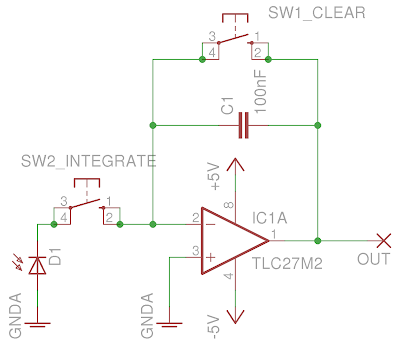
A nice method too read out the photo-diode would be to digitize the flash pulse intensity vs. time profile using a digital storage oscilloscope (DSO) and integrate the amount of light in software, but again, you need an expensive DSO to do this. A cheap solution is to integrate the amount of light in the flash pulse using an electronic integrator and then read out the result with a volt meter. An integrator is a small circuit using an operational amplifier chip, which stores charge in a capacitor, producing a voltage that is proportional to the total amount of charge that flows into it, ideal for this application. Pretty much any op-amp will work, but those with FET input transistors work best, since they draw almost no input current and have very low bias and offset currents, to which integrators are particularly sensitive. A typical integrator circuit is shown below.
I used the Texas Instruments TLC27M2A1 opamp in this circuit and was very happy with the results. The charge in the pulse is integrated while switch SW2 is held closed. The pulse size is read as a voltage at OUT. Switch SW1 clears the charge on the capacitor, zeroing the integrator for the next flash pulse. Ideally D1 is a photo-diode, but any regular LED will also work. To cover a large range of flash pulse sizes it is convenient to be able to change the value of C1 - an IC socket into which the capacitor is plugged makes this easy.
The plot shows the integrated charge from the photo-diode for a Nikon SB-25 and SB-600 strobe set in manual mode. The strobes were set to full, 1/2, 1/4, 1/8, 1/16, 1/32 and 1/64 power and the photo-charge measured at each setting. The charge is plotted in stops -- a change of one stop corresponds to a factor of two change in the detected charge. With the exception of the full power setting on each strobe the amount of charge is linearly related to the manual power setting to within a fifth of a stop. For each strobe the full power setting is almost a half a stop above the expected value. I have no explanation of why this is.. my guess is that it is difficult for the manufacturer to control the discharge of the capacitor at the full power setting, and this is the best the could do.

The results of using the a time delayed TTL quench with the SB-25 and SB-600 is shown in the second graph. The plots shows the amount of photo-charge measured as a function of the delay between the trigger and quench signals in milliseconds. The flash pulse size is again shown as a fraction of the full-power pulse in stops. A few things are immediately obvious:
- The SB-600 can produce flash pulses over an amazing range of almost 14 stops. Fourteen stops is equivalent to ~1/16000! The lowest few points were hard to measures and there is considerable measurable error in the data.
- The SB-25 seems to flatten out at small quench delays. Presumably the electronics in the -25 are not able to stop the current flow from the capacitor quickly enough to produce very dim flash pulses.


No comments:
Post a Comment